Timing Side-Channel Analysis on an FPGA: A Digital Circuits Course Project
How an open-ended course project for Digital Circuits and Systems at IISER Bhopal turned into an experiment on timing leaks, legacy hardware toolchains, and designing secure logic.
 A course project for Digital Circuits and Systems at IISER Bhopal with my teammates Shubham Mohanty and Prashant Gupta.
Project presentation slides are available as a PDF.
Course Project Selection
When our professor announced the term project at the start of our Digital Circuits and Systems (DCS) course at IISER Bhopal, my friends Shubham Mohanty, Prashant Gupta, and I sat down to decide what to build.
The default route for digital design projects is familiar to most engineering students: digital stopwatches, basic calculators, or traffic signal controllers. While those are fine for practicing basic syntax, they feel like standard textbook exercises with predictable results. We wanted to work on something that felt closer to real-world engineering, where physical hardware behaves differently from theoretical software.
After reading into hardware security, we became interested in timing side-channel attacks: methods where secret information is extracted not by cracking mathematical formulas, but by paying attention to the physical time a chip takes to process data.
Hardware Selection and Toolchain Obsolescence
Unlike a standard microcontroller that runs software instructions sequentially on a CPU, an FPGA provides a blank canvas of digital logic gates. You describe hardware behavior in Verilog, and the toolchain configures physical circuits directly inside the silicon.
Finding a working board was our first practical hurdle. We initially borrowed a Xilinx SP605 Evaluation Kit from our department lab, powered by an older Spartan-6 chip. The physical board was in good condition, but getting it to communicate with modern laptops was difficult because its legacy design suite had been discontinued for years.
That experience highlighted an interesting truth about technology: hardware obsolescence is often a software problem. The physical silicon and routing on that board were completely healthy, but because the software ecosystem around it had moved on, the hardware was practically unusable.
To keep our focus on circuit design, we switched to the Shrike Lite FPGA. It was compact, interfaced cleanly over USB-C, and let us compile and flash our logic smoothly.
The Timing Leak Mechanism
In textbooks, digital circuits are modeled as ideal mathematical functions. For a 4-digit numeric PIN, there are 10,000 combinations from 0000 to 9999. In pure theory, an observer without the password has no shortcut and must test combinations one by one.
However, physical chips run on real clock ticks. When programmers or hardware designers create a password check, natural intuition says to compare digits one by one. If the first digit is wrong, exit immediately to save time; if it is right, move on to check the second digit:
Is digit 1 correct? No  -> Reject immediately (takes 1 tick)
Is digit 1 correct? Yes -> Check digit 2...    (takes 2 ticks)
In general-purpose software, that early exit is considered efficient. In security, however, it is a leak. An input with the correct first digit takes slightly longer to reject than an input with an incorrect first digit. The physical chip unintentionally whispers clues through execution time.
Bench Implementation and Results
We implemented our verification circuit on the Shrike Lite FPGA, embedding the secret PIN 7352. To make the timing differences directly observable on our desk without an oscilloscope, we linked an onboard LED to pulse with the internal clock cycles of the verification check.
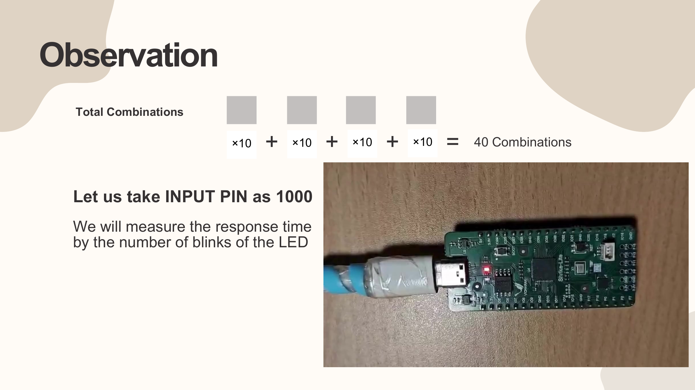 Our workbench setup: testing inputs on the Shrike Lite FPGA board.
We fed test inputs through a serial terminal on our laptop:
- Inputs starting with
1000,2000, or3000produced a single LED blink before returning an error. - When we entered
7000, the LED blinked twice. That extra tick confirmed that the first digit was 7. - Keeping 7 fixed, we swept the second digit:
7100and7200gave two blinks, while7300produced three blinks, identifying 3. - Following the same pattern, we found 5 with four blinks, and finally entered
7352. The LED stayed solidly on, indicating that the system was unlocked.
Instead of testing 10,000 combinations, we recovered the complete PIN in under 40 attempts.
Observations on Hardware Security
Building this project on silicon highlighted practical principles that rarely stand out in slides:
- Early exit is a security vulnerability: Stopping computation early saves time in standard software, but in secure hardware, constant-time execution is mandatory. Every input must take the exact same number of clock cycles regardless of whether it is valid or invalid.
- Hardware parallelism as a defense: In software, running checks in parallel involves heavy threading overhead. In hardware, true parallelism is natural. We resolved the timing leak by comparing all four digits simultaneously using parallel XNOR logic in a single clock cycle, ensuring every guess takes identical time.
- Physical execution matters: As dedicated hardware accelerators and edge devices become common, security cannot focus solely on software bugs. The physical signals emitted by hardware, including timing, power, and heat, are measurable realities.
A special acknowledgment goes to my friends and teammates, Shubham Mohanty and Prashant Gupta, for bearing with me throughout this project and seeing it through together.